
![[PCB Review Request] A choc-spaced 56 key wireless build](https://lemmy.world/pictrs/image/da52a9d0-adef-4700-98df-0d3bda9f5735.jpeg)
Hey everyone!
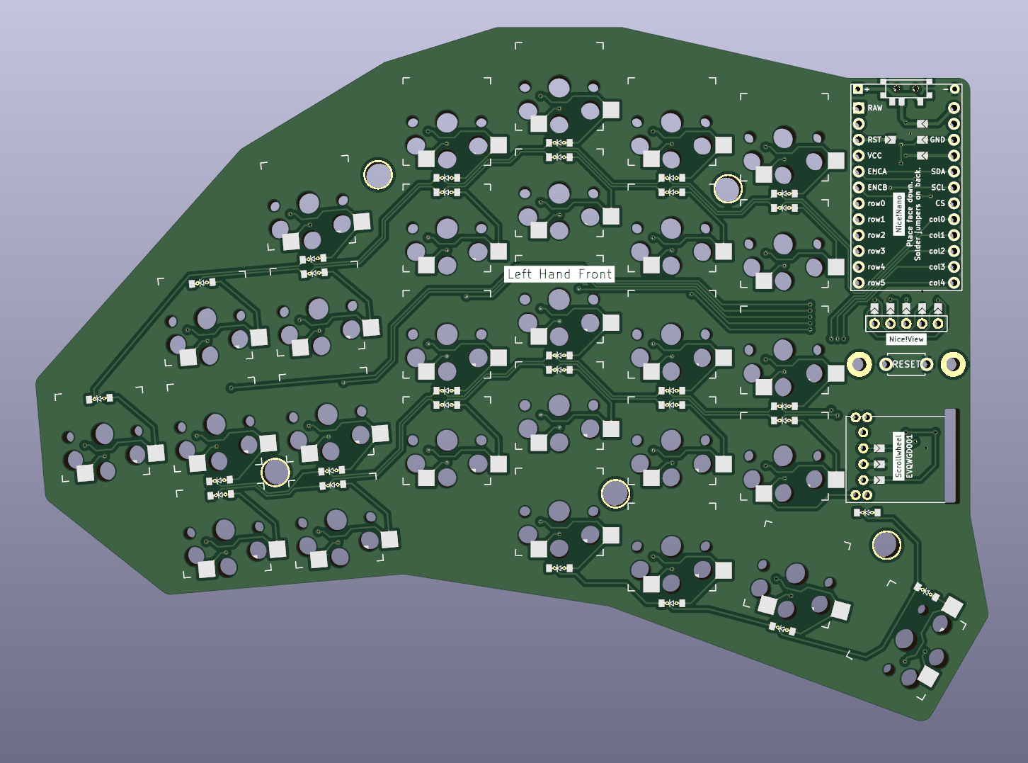
I jumped into the ergomech rabbit hole sometime last year and after using a sofle as my daily driver since then, I now decided it’s time to build my own “thing”. After going through endless revisions to figure out what I actually want, and trying to learn how to trace PCBs, this is what I have come up with: A choc-spaced 56 keys wireless build with a scrollwheel and some staggering.
It’s a reversible PCB. To make this work with single pin hole for both sides, I used jumpers for pins that can not be set in software (VCC, GND, RST). For rows/columns, I plan to do a different mapping in software to not have a jumper for every single pin.
All files including the kicad_pcb and ergogen config are available and open source at github: https://github.com/dnlbauer/splitkeyboard .
However, this is the first thing I ever designed. Therefore, I was hoping if you guys could have a look at the PCB before I get it etched and point out if there are any obvious errors?
Of course, I am also happy about any feedback in general. :)
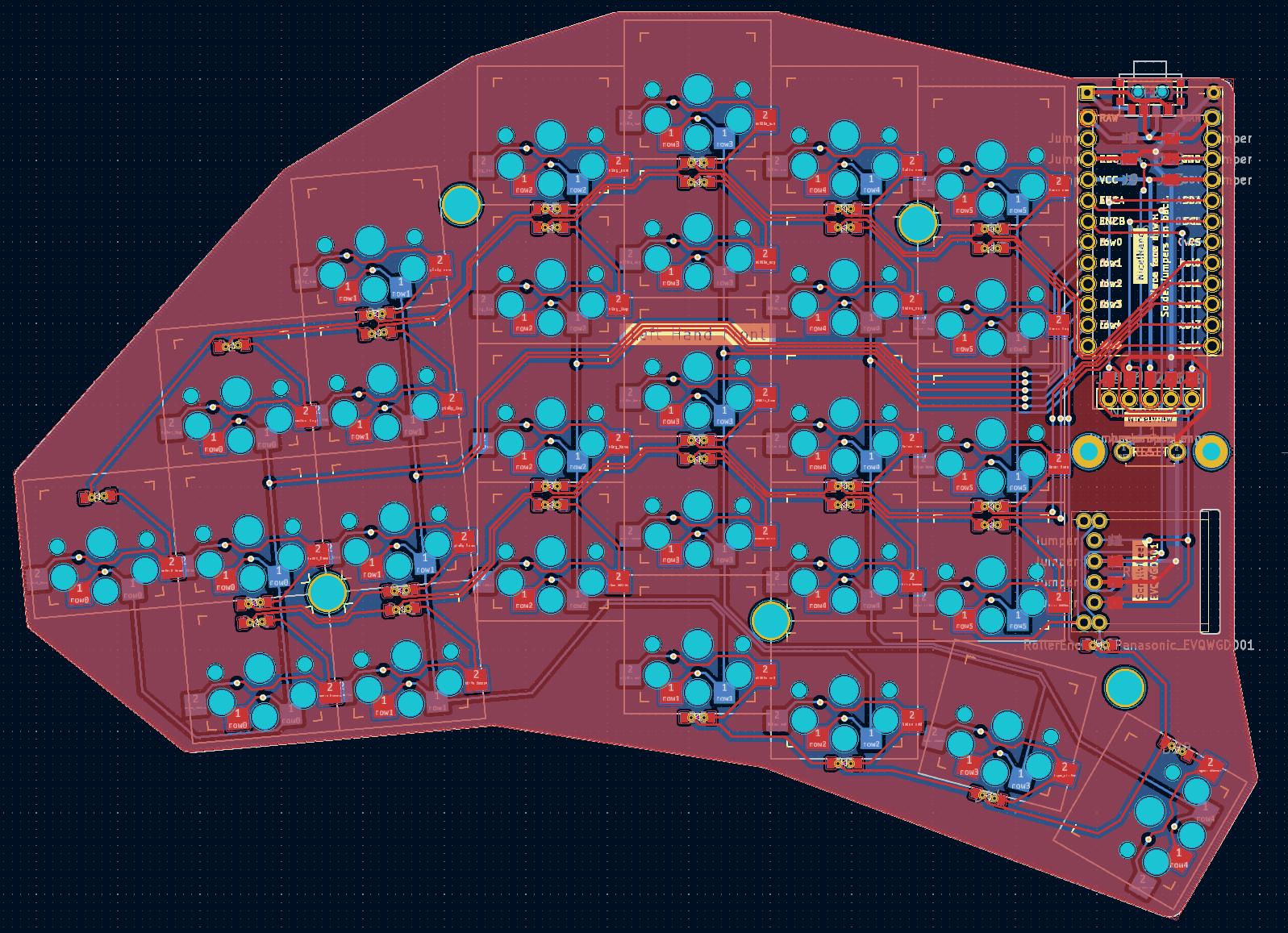
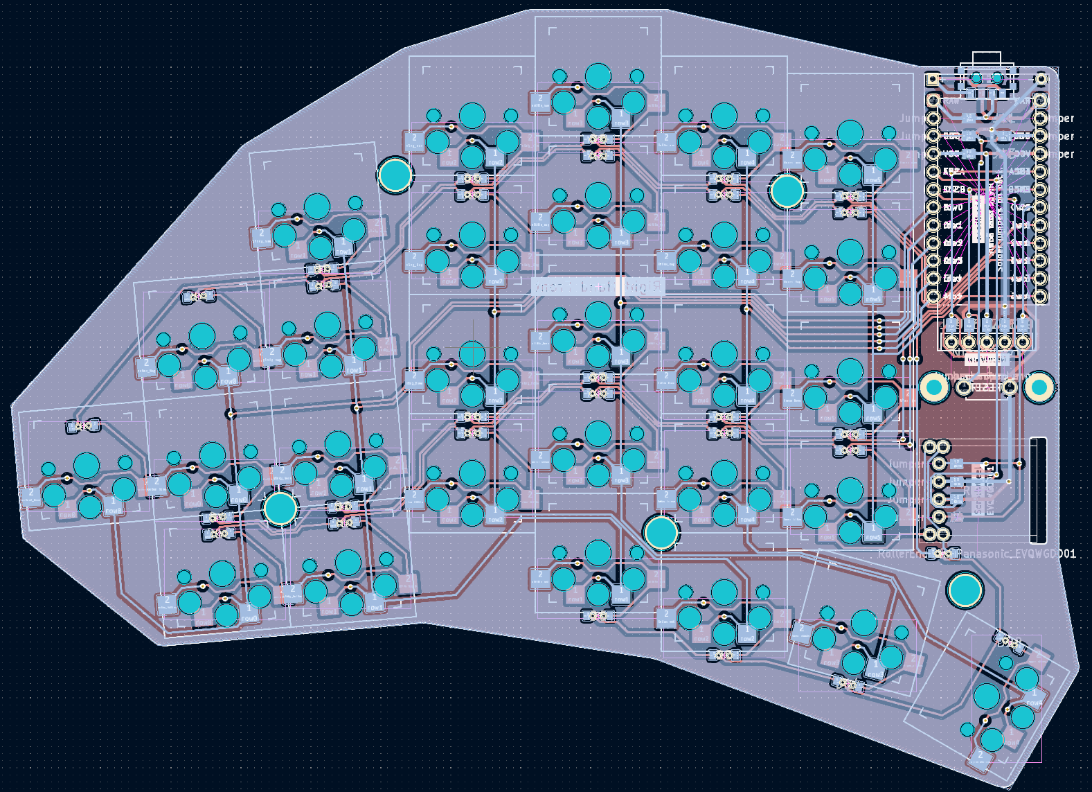
Yeah just some vias for return to ground; everything looks reasonably fine from a quick overview. You have space, and cross talk really isn’t a concern, but more padding between signal traces could be helpful in some of the closer areas. Though all of that is minimal in concern.
I just kept the default value (I think its 0.2mm) between traces. I could probably double it at some points where multiple traces are bundled though. Thanks for the hint!