
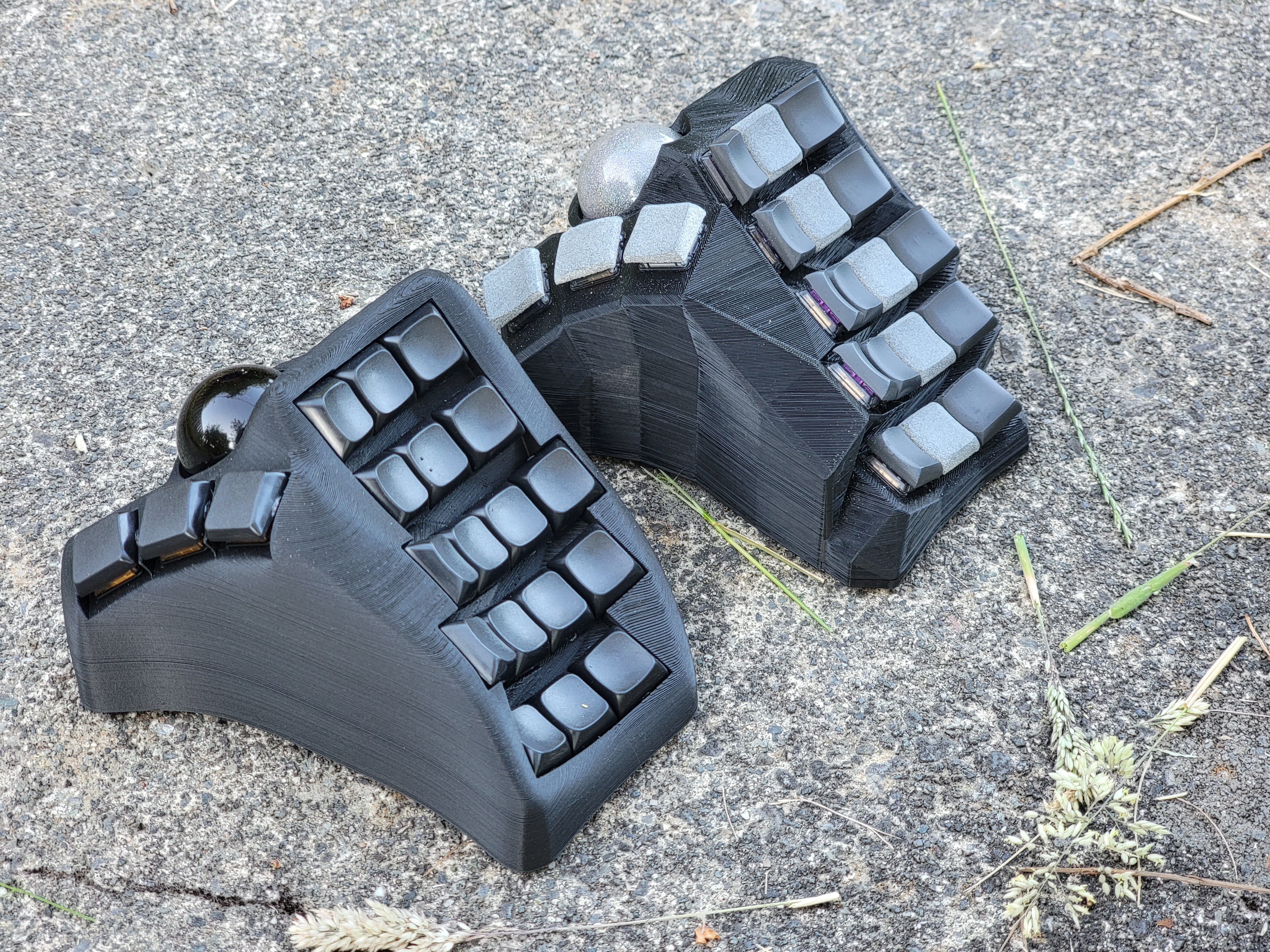
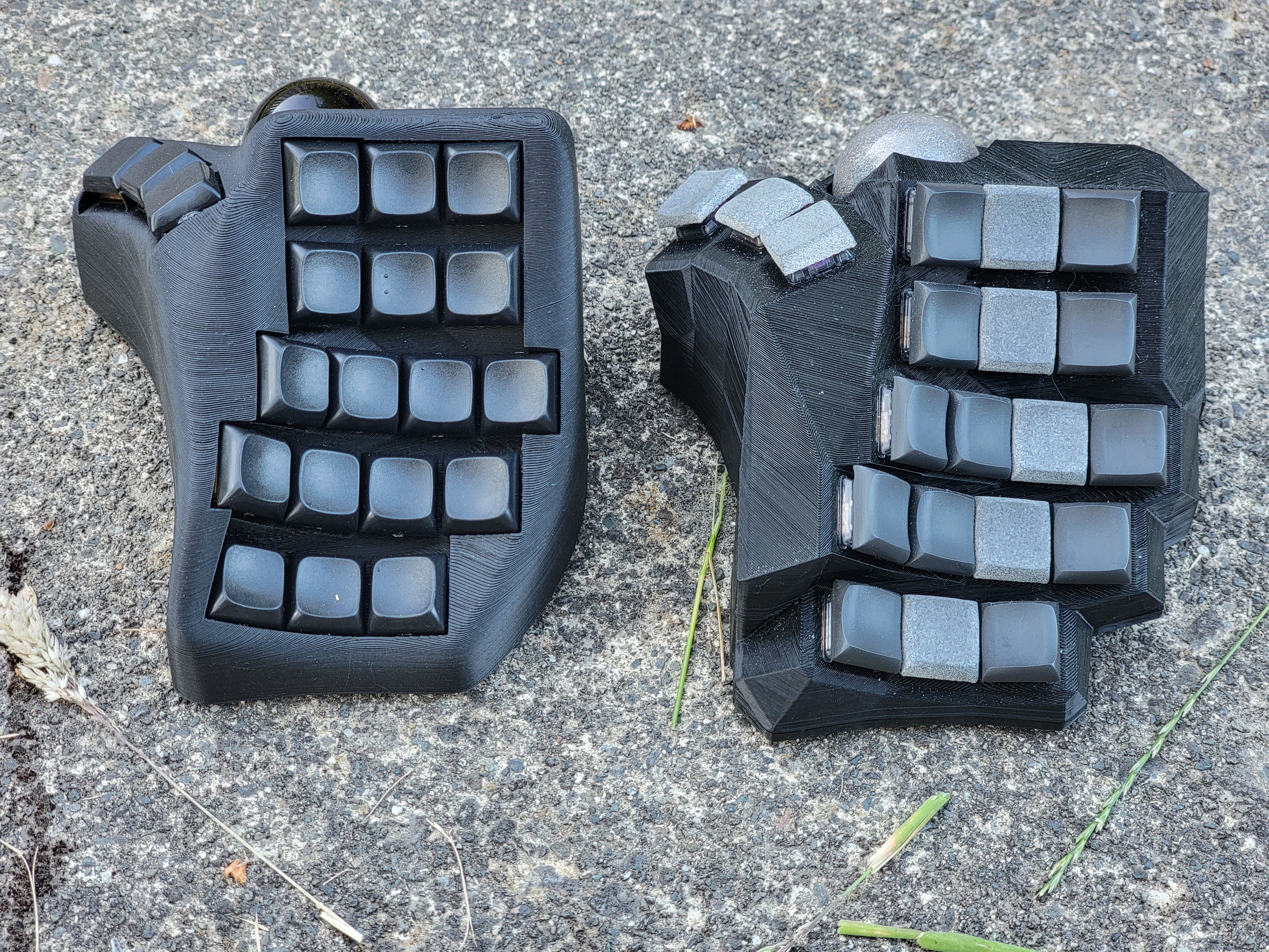
Old version in the back, new version in the front. Fresh off the printing bed. Haven’t tested it yet, but pretty happy on first inspection. Have a few sneaky features. Aiming to release it in a month or so to the community. Using it as an excuse to try out Lemmy :-)


I’m just starting with all this (I’ve ordered a kit, but still don’t have it even), and this made me wonder: what’s the wiring for something like this? Is it a flexible PCB, severall small PCBs, a flat PCB with some kind of positioning adapter on the switches, just raw wires, or something else I can’t think of? And whichever the answer is, is it the same as what’s done for professionally-made ones like Kinesis’s?
There’s options for everything you listed. If you check out Bastard Keyboards, they have designed a pcb that flexes to the curvature of the columns, but as you could imagine, this is custom to the key row and column spacing. Another option is a single key pcb, often called an amoeba. There’s a bunch of variants, often with an RGB LED under the key. Even more simple is to just flywire the whole thing. The base requirement for each switch is a single diode, so there’s not much under the hood. A good practice that I’d recommend is using a hotswap socket so you can try different switch types or transfer the whole thing to another case…this is essential when developing and iterating a case such as this one. There’s a lot of options for flat split boards, and the base is often a PCB with all the traces and pads for the diode, LEDs, MCU etc. These are much easier to build, but obviously don’t have the contour foe the hands. I believe, though can’t be certain, that the kinesis uses a flexible pcb for each column, similar to the bastard keyboards.