
Hello! It has been a week! I did some work on this! Not as much as I’d have liked because I’m sick (I believe not COVID, it’s been fairly mild and if it is COVID my vax is fresh but I’m still avoiding doing a lot).
What I’ve been up to
The main engineering achievement of the week was finishing drafting a schematic for the timing part of the circuit. Brief step back, in terms of development, I am breaking the first version into 3 separate pieces: the power board, the current pump frontend, and the timing board. I’m doing this so I can debug them all separately; if one of them ends up being broken and I need to wait on a new PCB or components, it doesn’t block me from working on the other two. Once they all work, I will unite them all into a single PCB that will form the final version of the first release. The timing board is the most complicated of the three, and it itself breaks down further into three more parts (all on the same PCB). These are:
Power conditioning:
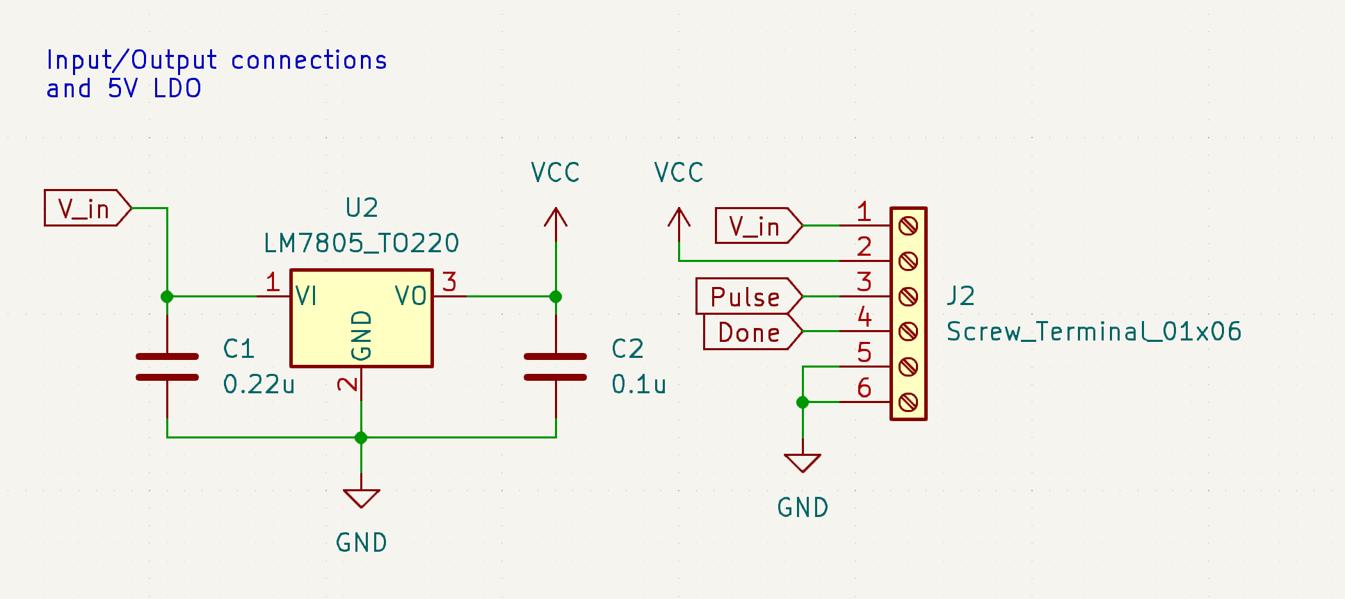
All this is is connectors to hook up inputs and outputs and a basic voltage regulator to turn the input voltage into a clean 5V to do logic circuitry with.
Pulse timing:

This is the part of the circuit that activates the current pump I drew, layed out, and ordered from my previous post. This thing has a 6.35mm jack that you plug a sustain pedal from a keyboard into (deeply proud of this idea - transfems are literally known for their audio equipment!), and on press, it will start a 5V pulse that is anywhere from 1.5 seconds to 12 seconds long, depending on the position of knob RV1. This 5V pulse will activate the current pump frontend. Notably, I am not using a 555 timer. I spent so. much. fucking. time on this fucking part of the circuit, the 555 was utimately to imprecise to feel good about including it. I was going to use a fucking crystal oscillator to keep good time at one point, and then finally I luckily found out about the LTC6993, which is an awesome 555 replacement that every amateur electronics person should get comfy with because I am never using a 555 ever again. There’s still fairly sizeable error from RV1 being +/- 20% tolerance, but at least it’s not stacking up from several parts, depending heavily on temperature, or any of the other problems a 555 has. This part would be a thousand times easier with a microcontroller, but at least it doesn’t need to be flashed. @macerated_baby_presidents@hexbear.net you tried to warn me and I didn’t listen lmao
Feedback
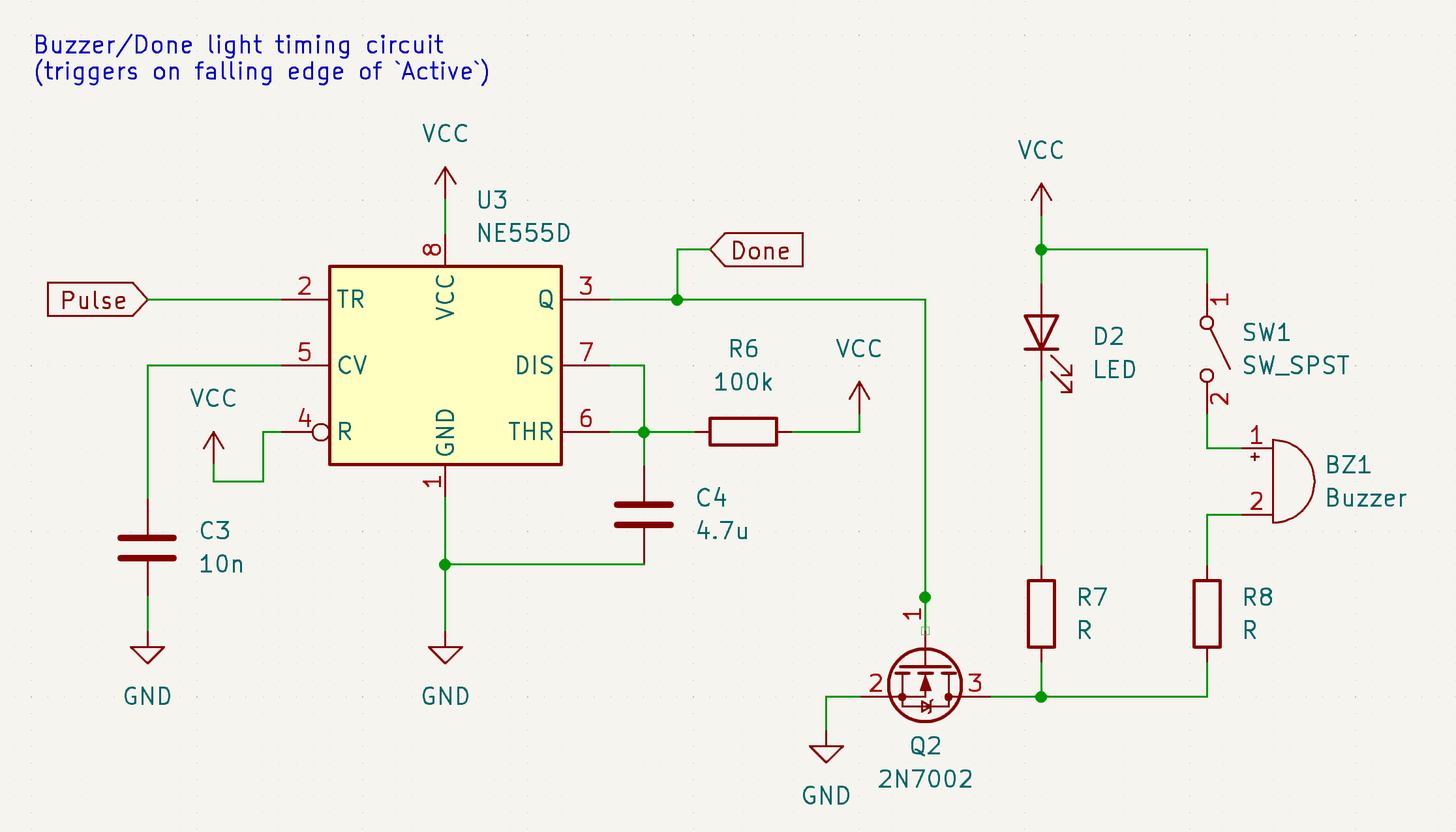
Basically, as soon as the pulse is done, this board will turn on a little “OK!” LED and, if the switch is on, make an audible beep. This one can be a 555 timer because I don’t care precisely how long the beep is. Right now it’s about a half a second.
These three are all on one board. I still have to identify components to use for some of these (LEDs, buzzer, switch, 6.35mm jack, maybe more?) before I can lay out an actual PCB like I did for the current pump, but that’s what I have coming up next.
That’s been my week! Not a bad run if I do say so myself.
New Developments
First and foremost, I made some tough choices about how I want to plan things going forwards. I have a long and often times self-conflicting priorities list, so I wanted to come up with a road map that satisfies as many of the goals of the project as possible. So, the road map going forward from my side will be as follows:
- First, I’m going to make a push to release the first iteration, the minimum viable product to providing safe, accessible, and effective electrolysis for anyone who wants to make one, with no bells and whistles. This will have a lot of cuts (full list below) but it’ll be 100% sufficient to perform electrolysis with and I’ll only release it when I’ve confirmed that it works and it’s safe. I’m going to be calling this version the Sphynx Lite.
-
- From here, once the Sphynx Lite is released, things open up for contributors to do more things for the project. This is where I’d love a couple of particularly passionate and initiated folks to get involved and start doing things like writing documentation, designing enclosures, revising the circuit to release a Sphynx Lite 2, and more. Hopefully with the board and a minimal instruction manual I’ll provide for its operation and making rudimentary peripherals, we can get an ecosystem going.
- Once the Sphynx Lite is out, start work on the Sphynx Uno (Sphynx Ein? just “Sphynx”? Sphynx один? still workshopping this one a lil bit) that will roll in all the nice to haves that I left out of the Lite, while keeping a lot of things I’ve put effort into and would like to keep, like the current pump.
-
- With the Uno, there’ll be firmware - this is where community folks will really be able to shine, for one, this is the thing that the most people expressed interest in helping with, and for two, this is the thing that allows development to be distributed, people to work on multiple things at a time, and the project to really start picking up steam.
- Once the Uno is on a clear trajectory across the finish line, that’s when we can start working on the final boss, the Sphynx Wave.
Rundown of the 3 models I could ever imagine intending to make:
- Sphynx Lite: Takes 2 9V batteries. No microcontroller, no screen, likely not even a 7 segment display unless there arises a good safety argument for needing visual feedback on voltage and current, just a knob for max current, a knob for max voltage, and a knob for pulse time, with a beeper and a couple LEDs for feedback, and connectors for a foot pedal activation switch and a probe. All digital and analog electronics - no flashing required.
- Sphynx Uno: Add a microcontroller, rehash a lot of things that will benefit from having a microcontroller, like timing, input method, and whatever else comes up. Replace the 2 9V batteries with a LiPo with a proper power infrastructure, including boosting, possibly to a slightly higher voltage than the Lite, USB charging, and more.
- Sphynx Wave: Everything that the Sphynx Uno is, except instead of just the DC current pump on the frontend, add an RF power applicator circuit to the output as well (this is nerd talk for “Uno is galvanic only, Wave is galvanic, blend, or thermolysis”).
(thank you to @lilypad@hexbear.net for suggesting the Sphynx name! I think I’m gonna keep it!  )
)
I’ve also decided that open hardware is probably the move licensing wise. It doesn’t preclude me ever getting something together to start selling units, but it also keeps this a community project and allows anyone to build it as cheaply as they want to, remix it, or do anything else they’d like to themselves.
Next Up
The components to build and test the current pump are waiting on my bench. I have to build that, test it, and then honestly I can fake the rest with an Arduino and a benchtop power supply to test the output parameters and kill a test area of hairs if there’s no bugs in my circuit and start the waiting game to see if they come back. I also have to lay out the timing submodule, and I have to both design and lay out the battery/power submodule. Once they all play nice tied together with wires on the bench, I’ll dump all 3 designs in the same file and start weaving them together to make the Lite.
Any ways to help?
Audit my circuits above for sure, I’m being dumb and ordering a PCB before testing most of this on the bench. I’m going to add some more debugging features to the design before ordering the design, but still it’d be nice to catch as many mistakes as possible early. I also have an interesting request:
Synoptic seems to be using a modified mechanical pencil as a probe - does anyone recognize this make of mechanical pencil? I’d love to get some and see if they lend themselves well to being made into probes. I owe you all an actual drawing of what the probe should look like and do next time too, it’d be awesome if someone could figure out how to make the probe work. If anyone feels like taking a stab at it now though, ask anything you’d like to know, but in short, all it needs to do is hold onto an F-shank needle with electrical continuity in a way that is easily replaceable and can be held like a pen. Bonus points if there’s some type of shroud to cover the tip when not in use, but that’s not a huge deal, it’s more important that this doesn’t require any advanced tools - accessibility.
Now that I’ve committed to a name, we can start thinking of a logo too! The added bonus of using a cat is that it’s extremely reasonable to incorporate a “:3” into the logo. I would love to see suggestions if anyone’s bored and looking to help! My only ask is that it should have a good monocolor representation and that it doesn’t have any tiny features so I can put it on the PCB itself. If you can draw it with a sharpie, it’ll work perfect.
If you have any questions, please ask below! It doesn’t matter if they’re technical or non-technical, it doesn’t matter if you think they’re basic, dumb, not worth my time, or anything else - I want people to get excited about this and I would love to take the time to communicate the inner workings of this to y’all so that everyone can be included! I can’t guarantee I’ll reply to everyone but I’ll do my best to reply to comments that are asking something directly or I have something to add to!
Tag list is in my top level comment below, reply to that comment if you want to be added or removed. Love you. Thanks for being here. I hope I can do good by my favorite internet people. :trans-heart:
Tags:
@Wake@hexbear.net @raven@hexbear.net @ForgetPrimacy@lemmygrad.ml @macerated_baby_presidents@hexbear.net @sharedburdens@hexbear.net @ComradeEd@lemmygrad.ml @BountifulEggnog@hexbear.net @YearOfTheCommieDesktop@hexbear.net @Erika3sis@hexbear.net @CarbonScored@hexbear.net @frankfurt_schoolgirl@hexbear.net @oscardejarjayes@hexbear.net @crosswind@hexbear.net @lilypad@hexbear.net @OurToothbrush@lemmy.ml @tartan@lemmy.ml @AernaLingus@hexbear.net @SnAgCu@hexbear.net
I added people who explicitly asked to be tagged or explicitly said they wanted to follow this project, but I didn’t add anyone who just said “this is really cool” or “I love this” - if you were in the latter group and you wanna hear what I’m up to about once a week, now’s your chance, reply here and I’ll add you!
I’d like to be added to the list!
added 🫶
yo! I will probably comment more thoughts and or hype but i think that pencil is some sort of pentel? not this exact one maybe but same mechanism: https://www.pentel.com/products/quicker-clicker-mechanical-pencil-with-grip
Okay. more thoughts on the mechanical pencil side of things: Still no dice on the exact one being used but I still think its some knock-off of the pentel I linked, or an older version of it. There’s also the skilcraft slickerclicker, which again looks similar but not the same.
From what you linked, the F shank is 1.25mm and K shank is 0.8mm. you could probably snugly fit those into 1.1mm(or maybe 1.3) and 0.7mm pencils respectively, since there is some margin of error in the collet. But it will need some testing. finding a 1.1 or 1.3mm pencil with a side button might prove annoying, but a 0.7 should be no problem (I think the side button is important since it allows you to gut everything above that point, but maybe other styles could still work). I’ve been looking all around and I think the pentel SideFX could maybe be a good candidate, or the other two I mentioned above. I could probably buy a few and see which one is easiest to gut and add a wire/connector to, but I’ll need to acquire some needles then too. Another idea is looking for a pencil with a retractable sleeve, but I’m not sure you could get one long enough to cover up the needle anyhow so it might be best not to bother.
ALSO: I absolutely KNEW I would need this industrial foot switch I bought at the surplus store a couple months ago. It was just too satisfying not to buy but I thought I would never use it… WRONG
This is extremely cool and I genuinely hope you achieve what you set out to do! Can you please keep me in the loop too? I’d love to follow your progress. Cheers
For sure, you’re in the tag list, thanks for stopping by
girls rock
I decided to just pull the trigger and buy some needles and a bunch of mechanical pencils. it’ll probably be a week before it’s all here but I’ll report back what I find in terms of making them fit and modding them for electrical connections (is soldering okay here? I guess that would raise the barrier to entry somewhat but it seems more reliable than just stuffing a wire in there… Maybe solid core wire the same diameter as the needle could be okay.)
Oh shoot this is huge, thank you so much for the initiative comrade! This is also something the /u/abbxrdy Reddit post has some wisdom on, in her post she says the following:
Probe housing is made from a d-sub female crimp pin soldered to a wire and covered with a piece of heat shrink tubing
This is my best shot at sourcing that. I’m pretty confident that this is what she used. Here’s the search I used if you wanna shop around. Probably best to get two kinds, I was also eyeing these nicer looking ones. They’re both super cheap, although it might be nice to grab a few, they can get bent up easy when you crimp them without a crimper.
Thank you so much for taking an active role on this I appreciate you more than you could know. If you wanna stay in touch, we can either use DMs here or I’ll make a matrix account or something. I’ll let you know!
Oh hey I didn’t see this reply in my inbox for some reason (so maybe matrix is a good idea, though I don’t mind keeping the discussion out in the open here either for the most part)!
Thank YOU seriously, I wouldn’t have the knowledge or initiative to do the electronics side of this at all properly like you are (I could maybe pull off a DIY-as-fuck version like that reddit post but even then)
I was hoping to use the actual mechanical pencil collet that it uses to hold the lead (usually brass iirc so good enough electrically) but db9 pins is a pretty clever idea too and easier to crimp or solder a wire to them… Probably keeping that in mind as a fallback if the pencil collet thing proves too fiddly. I just looked and I think standard db9 pins are a 0.04" so a hair over 1mm, but there must be enough flex in the receptacle side to accommodate a 1.25mm F needle? probably adds a lot of needed friction to do it that way, pretty clever and easy. Modding the pencil to securely hold the contact might be tough but gotta start somewhere… I have a lot of ideas now actually… thanks for the link, I may pick up some of those pins locally too.
Also, does using a K needle require AC or different current or anything drastically different than F? I picked up some of those too, but then realized you seemed to be talking about primarily just the F needles. (side note if you or anyone else here needs needles, I will have an abundance when these show up lol)
I pretty much made an instantaneous and arbitrary decision to use F-shank because of the /u/abbxrdy post. K-shank is just as good, maybe a tiny bit less ergonomic to install and change but tweezers will be necessary for use anyways so this isn’t a real factor. I only bought F-shanks, but if you figure out a good K-shank solution then I’m happy to switch!
A Reddit link was detected in your comment. Here are links to the same location on alternative frontends that protect your privacy.
Glad you got more done! Love the name and your plan for multiple designs.
Very cool. I would like to help, but my technical prowess lies a lot “higher”, e.g. python and html, and not very artistic.
Hey I’m happy for you to just hang around! At some point it’d be nice to have an online manual hosted somewhere, maybe you’d be able to get some content up on readthedocs or some other python-y wiki-like platform? We’re def not ready for that yet but it’s definitely coming up in a month or two
maybe you’d be able to get some content up on readthedocs
That was what I was thinking. And sure, I’ll help with that.
Also can’t wait to try the doohickey itself.
LTC6993 looks clever. I am guessing it isn’t made for manual control of RSET, because using a potentiometer as a rheostat sucks and it would be easier if you could use a fixed resistor for broad control and do fine control via a potentiometer voltage divider. With this circuit, if you have a ±20% pot (which I do think you could get down), you’re going to get a minimum time that’s set by R3 (nice and precise) and a maximum time that’s set by RV1. This is the opposite of what you would want for safety: 0.5s vs 0.6s is less important than 5s vs 6s at the top end. Worse, the failure mode - if the pot wiper comes off the track / if a spec of dust gets in there or whatever - leaves VSET floating at 1V and:
The output pulse will continue indefinitely if ISET drops below approximately 500nA
Ideally this would be backward: full disconnect yielding a 0s pulse and turning the potentiometer all the way to 0Ω (so it’s just your high-precision fixed resistor to ground) yielding the desired max time. I’m about to fall asleep but maybe there’s a way you can make this better with negative output mode and/or have the probe a current sink instead of source, or something.
I tried and failed to come up with a way to use the potentiometer as a wiper so that the total resistance of the pot doesn’t matter. Maybe you could put a regulated current sink here? They also have an example circuit for “voltage controlled pulse width” which could be helpful if you can get a voltage source to sweep across without it being too annoying. I don’t think it’ll break if you put more than 1V on it but I don’t understand what happens to the pulse with “negative” ISET. They suggest buffering the 1V for a DAC that accepts a reference voltage but IMO that’s heading into overkill territory.
you could also have a failsafe of a second, fixed pulse generator that limits the max length. Either a clamp on the main pulse or an AND type thing with the trigger input. High parts cost though.
You’re so right bestie, if I’m being honest, I was so exasperated and tired and sick-brain when I did that part of the schematic. I remember thinking that was a problem but deciding it was good enough, which was a very bad call in hindsight. I need to revisit it. I’m still sick brained and probably more exhausted so that’s a tomorrow thing, but I very much appreciate you auditing my work and checking the datasheet, I totally missed figures 8 and 9 which both look like excellent options for this use case. LTSpice exists too, so this should be fairly straightforward to model. I’ll overhaul the pulse timing soon. Thank you for being here and being involved.
o7
Honestly if I was making and using it on myself I wouldn’t gaf but for distribution I guess it matters. Good luck, timing is so fucking annoying I’m learning from your work too