
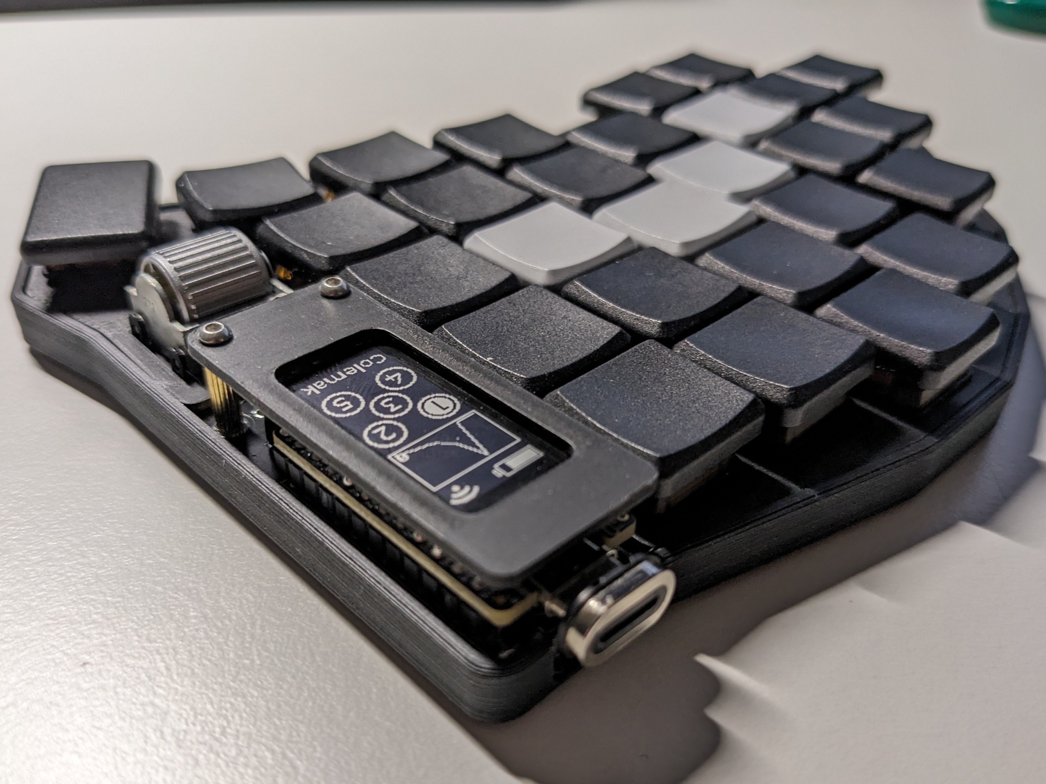
My first design! Github link to the repo with pcbs and 3d printed components: https://github.com/dnlbauer/corax56-keyboard
You must log in or register to comment.
I agree with the commenter who said they thought it could be a commercial project, it looks incredibly clean
thank you!
Great work, looks like it could be a commercial product. I’m still not sure if I want choc V1 or V2, but if I go with V1, this might very well be the build I copy.
Aww crap, I might have to build another mechanical keyboard.
This hobby in a nutshell.
Having had the PCBs printed, have you tried regular profile switches or do they make it look weird?
Looks great with the low profile ones!
Haven’t tried regular-sized choc switches before, but they should work. One thing to consider would be that with the heigher switches, the scroll wheel might be harder to reach with the thumb because it might be physically hidden behind enter/space. Should not be a problem if you are used to use the index for the wheels though.
This is awesome, I have a similar design coming from JLPCB this week (it is a bit more Corne like though).
Any advice or important lessons you learned?
The main lesson I learned was probably to start thinking “in hardware” and not software. Like you design something and it fits on paper but in reality, it might not be ideal. For example, my diode placement is very close to the hotswapsocket (i fixed that for rev 1.1). On paper it war fitting, but its kinda hard to solder when you need room for your solder iron in between - this is something kicad won’t tell you.
Thanks. I must admit I am curious to see what mistakes I’ve made this coming weekend. My first KiCAD PCBs should arrive this week, then the penny shall drop I suspect.
If you’ve not tried it yet I’d recommend having a go at reflow soldering with a hot plate. It makes some aspects of assembly easier.
I haven’t yet had a chance to get two rotary encoders working under ZMK yet either. Did you have a good resource to use for that or did you need to figure it out yourself?
(Appreciate I’m asking a lot of questions sorry).
EDIT: I see you’ve posted your ZMK config, nice 😊
There is a zmk pull request open that adds split encoder support. If you use that to build your firmware if should work.
To be honest I have not tried it with this board so technically one scrollwheel is not working right now. Though I’ll change that soon. I used a fork that supports split encoder with zmk on my sofle and it worked, so you could use this config for some inspiration (here: https://github.com/dnlbauer/sofle-zmk-config).
Awesome, thank you.
I have a Sofle to test with ahead of assembly. Also “my design” is based on the Sofle (electrically at least), this is super helpful!
deleted by creator
Looks awesome! I like how you designed the pinky cluster! I don’t think I’ve seen that before on a board with 6 columns
You might also like the Steel Tormentor. There are some really nice write ups about the process, too.
there is another one that does something similar but that is not open source as far as I can tell: https://github.com/sprengboard/choccy
That’s a beast! Looks great. The scroll wheels make a lot more sense to me than the inspirational ones you linked to in the github that have knobs near the thumbs. Course I guess the knobs are intended for the thumb and maybe scroll wheel would be pointer finger. Scroll wheel looks better imo.
I use my thumbs for the scrollwheels. My previous build was a sofle but the knobs always bothered me. They stick out too much, make it hard to transport the keyboard and I got into a habit of turning them with my thumb+index, so leaving the home row. With the wheels, using them feels much more natural!
Phew, that scrollwheel (EVQWGD001) is pricey. Raging between 8-15 EUR.
That’s because of scalpers, they aren’t produced anymore alas. Someone on the Reddit mentioned wanting to make an alternative to that scroll wheel but I don’t know if it went farther than just designs maybe.
yeah they are a bit expensive. But they are worth it imho. Scrolling with the thumb on them feels very natural and the height is very similar to the chocs!
That’s a cool looking board!
so you need to flip the nice!nano on the other side?
No, you solder it in the same way for both sides.
The “flipping” is handled mostly internally. For The right hand side, the firmware just maps the rows and columns differently than for the left hand side. For pins where this is not possible (Vcc, Gnd,…), there are jumpers on the other side that need to be soldered.

